Phasics
- Wavefront, MTF and QPI measurement solutions
- Products
- Applications
- Markets
- Company
- Contact us

Aug. 19, 2026
In lens assembly and alignment, it's a familiar frustration: the lens was built exactly to the assembly process, every dimension is within tolerance, spacers match the design, threaded rings are torqued down, and a visual inspection shows no obvious scratches or dust. Yet when it goes on the MTF test bench, the result comes in 10%–20% below the design value at specific spatial frequencies and sometimes worse in certain azimuths.
This scenario is extremely common on the alignment floor. In practice, finding the root cause often takes longer than discovering the problem in the first place. This article walks through the main causes of MTF shortfall after lens alignment, focusing on engineering-level diagnostic logic rather than optical design tolerance theory.
1. The Underlying Logic of MTF Shortfall
MTF describes an optical system's ability to transfer contrast, and at its core it is a composite expression of wavefront aberration. Any MTF degradation introduced during alignment is, fundamentally, an increase in wavefront error.
Errors introduced during alignment generally fall into three categories:
These three error types combine and ultimately show up as reduced MTF at the detector plane. Understanding this underlying logic keeps the diagnostic process pointed in the right direction.
2. The Most Common Culprit: Decenter and Tilt
Decenter (lateral displacement of the optical axis) and tilt are the leading causes of alignment-induced MTF degradation and also the most easily overlooked, since unlike axial spacing error, they can't be measured directly with a feeler gauge or dial indicator.
2.1 Sources of Decenter
MTF signature of decenter: Decenter primarily introduces coma, showing up as asymmetric MTF between meridional and sagittal directions, most pronounced at the edge of the field. Central-field MTF may remain close to design value while off-axis performance degrades noticeably and rotating the lens rotates the direction of the degradation with it.
2.2 Sources of Tilt
MTF signature of tilt: Tilt primarily introduces astigmatism, seen as a separation between meridional and sagittal MTF values. At the focal plane, the point spread function (PSF) shifts from circular to elliptical.
3. Axial Spacing Error
Axial air-space error is a major consideration when allocating tolerances at the design stage, but it's still easy to introduce out-of-spec spacing during assembly.
3.1 Typical Sources of Spacing Error
3.2 Effect of Spacing Error on MTF
Axial spacing changes primarily disturb the aberration balance of the system. At the design stage, aberrations from different groups are meant to compensate one another; a change in spacing breaks that balance and increases residual aberration. The typical signature is a uniform MTF drop across the full field, or for zoom lenses inconsistent degradation across different focal positions.
4. Surface Deformation from Assembly Stress
This is a factor that's often underestimated in real-world engineering.
4.1 Surface Change from an Over-Tightened Retaining Ring
When a retaining ring applies axial clamping force to a lens, that force is transmitted to the seat through the contact surface, producing bending deformation. For large-diameter, thin lenses (diameter-to-thickness ratio > 6:1), the annular force from the retaining ring can significantly change the surface form, introducing spherical aberration and astigmatism.
Example: A φ60 mm plano-convex lens with a design thickness of 5 mm (diameter-to-thickness ratio 12:1). After the retaining ring was tightened, interferometer measurement showed the surface PV value change from 0.2λ before assembly to 0.6λ afterward, resulting in an MTF drop of roughly 15% at 80 lp/mm.
Diagnostic approach: Remove the retaining ring and re-measure the lens surface, comparing it against pre-assembly data. If the surface form recovers, stress-induced deformation is the primary cause.
4.2 Residual Thermal Stress
Assembling a lens in a high-temperature environment (for example, during the curing process after optical bonding), or shrinkage stress from adhesive curing, can leave residual stress in the lens element and alter its surface form. A lens that passes MTF testing at room temperature but degrades after thermal cycling is often affected by this issue.
5. "False Failures" Introduced by the Test Setup Itself
Before troubleshooting the alignment process, it's worth first ruling out problems with the MTF measurement itself. Several conditions can produce a falsely low result:
5.1 Focal Plane Not Accurately Positioned
MTF is extremely sensitive to defocus. Near the design's Nyquist frequency, just 10 μm of defocus can cause MTF to drop by more than 20%. Inadequate focal-plane alignment during testing is the most common source of a "false failure."
Troubleshooting method: Scan multiple points near the focal plane to find the MTF peak position, and use the MTF at that peak as the basis for judgment.
5.2 Test Target Alignment Error
In slanted-edge MTF testing, deviations in edge angle or in the perpendicularity between the target and the optical axis both affect measurement accuracy. When the edge tilt angle deviates from the recommended range (typically 5°–7°), the MTF calculation error increases.
5.3 Stray Light and Environmental Vibration
Stray light in the test environment raises the detector's background signal and lowers measured contrast. Bench vibration broadens the PSF, pulling the MTF curve down.
Basic checks: Block the light source and verify the detector background matches expectations; capture and average multiple frames during MTF testing and check the result's stability.
6. Recommended Diagnostic Sequence
When facing an MTF shortfall, it's best to troubleshoot in order from low-cost to high-cost, and from non-destructive to destructive methods. The core logic of this sequence is: first characterize (the spatial pattern of the MTF result), then localize (which aberration type is involved), and finally pinpoint (which step in the alignment process introduced it).
7. Engineering Details Worth Noting
Don't be quick to blame "insufficient design margin." Alignment engineers often attribute MTF shortfall to overly tight optical design tolerances, but in most real cases, the alignment process itself is the primary cause. Design tolerances assume ideal process conditions,no amount of tolerance margin helps if the process execution falls short.
Consistency in retaining-ring torque. Retaining-ring tightening torque should be controlled with a torque wrench, not by feel. In batch production of the same lens model, torque consistency directly affects MTF consistency across the batch.
Alignment environment temperature. If alignment is performed at 20°C but testing happens at a different temperature, thermal expansion of the metal barrel changes lens spacing and seat fit, causing test results to diverge from the as-assembled state. Precision lenses should be aligned and tested in a temperature-controlled room.
Effect of cleanliness. Fingerprints, oil residue, or dust left on a lens surface introduce scattering at specific spatial frequencies, reducing mid-to-high-frequency MTF. Final cleaning should be done in a cleanroom, and internal light transmission should be checked afterward.
MTF shortfall after lens alignment doesn't always have an obvious cause. Decenter and tilt are the leading alignment-induced sources of aberration, but accumulated spacing error, assembly-stress deformation, and issues in the test setup itself are just as important not to overlook. The key to diagnosis is learning to read the spatial pattern of the MTF curve, it's the "signature" of a specific aberration type, and it can point directly to the alignment step responsible. Matching that signature to the alignment workflow significantly improves troubleshooting efficiency.
Alignment is one of the most experience-intensive areas of optical engineering but that experience should be built on a systematic physical understanding, not just repeated trial and error.
Struggling with MTF Shortfall on Your Alignment Line?
If your lenses are meeting mechanical tolerances but still failing MTF, the root cause is often hiding in the wavefront, not visible under a standard visual inspection.
Phasics (an Exosens company) designs quadriwave lateral shearing interferometry (QWLSI) wavefront sensors for optical alignment diagnostics:
This approach has already been applied by leading cinema lens manufacturers, using a PHASICS SID4-HR to characterize highly aberrated zoom-lens sub-assemblies presenting more than 30 μm PV of design spherical aberration at F/2.
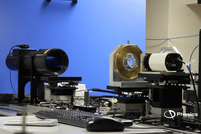
Figure 1: PHASICS test bench used for the characterization of cinema zoom-lens sub-assemblies.
The principle is to compare the measured wavefront with the theoretical wavefront calculated from the optical design. The measured wavefront contains the nominal design contribution, the residual contribution of the measurement bench, and the residual WFE associated with the manufactured optics.
In this application, the test-bench contribution was kept below 100 nm PV, allowing residual optical errors in the 130–700 nm PV range to be distinguished from a much larger nominal design aberration.
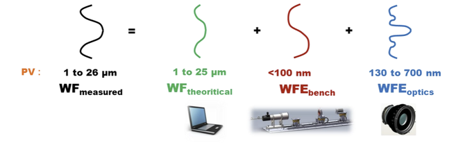
Figure 2: Decomposition of the measured wavefront into theoretical, test-bench and optical contributions.
Once the nominal design contribution is separated, the residual WFE provides information about the manufactured optical assembly. Measurements across different lens sub-assemblies can therefore reveal variations and abnormal groups associated with production, helping identify potential manufacturing issues before final integration.
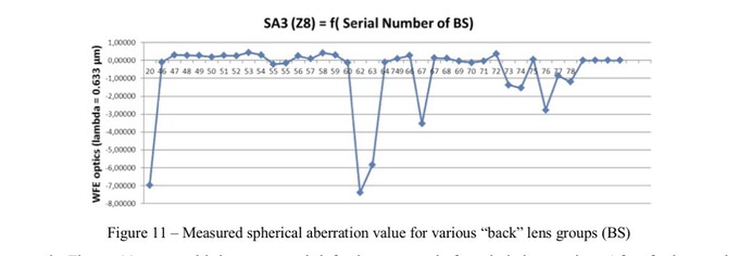
Figure 3: Measured spherical aberration (Z8) across different back lens groups, illustrating how WFE measurements can reveal abnormal sub-assemblies during production.
This enables problematic sub-assemblies to be identified earlier and supports pre-alignment before final zoom integration, facilitating the subsequent alignment process.
Whether you're debugging a one-off alignment issue or building a batch-consistency process for volume production, our team can help you design a test and diagnostic workflow around your specific lens architecture.
📩 Get in touch with our team to discuss a wavefront/MTF diagnostic solution for your application.