Phasics
- Wavefront, MTF and QPI measurement solutions
- Products
- Applications
- Markets
- Company
- Contact us
Feb. 17, 2025
Unlike superconducting or photonic quantum computing approaches, trapped-ion quantum computers require the integration of multidisciplinary technologies, including vacuum systems, laser and optical systems, radiofrequency (RF)/microwave engineering, and coherent electronic control. Industry leaders in North America have now surpassed the 20-qubit milestone and are advancing toward practical applications.
How are ions trapped and controlled?
First, individual or multiple ions are stably confined within a trap, forming a linear or two-dimensional ion chain. This is achieved using a Paul Trap (Figure 1 and 2) or Penning Trap, which generates a dynamic potential well through RF and static electric fields, balancing the ion's motion via electromagnetic forces. Commonly used ions include calcium (Ca⁺), barium (Ba⁺), and ytterbium (Yb⁺) due to their energy level structures, which are suitable for laser manipulation. The stability of ions in an RF trap depends on the time-varying potential and parameters such as the ion's charge-to-mass ratio, RF frequency, RF amplitude, and potential curvature.
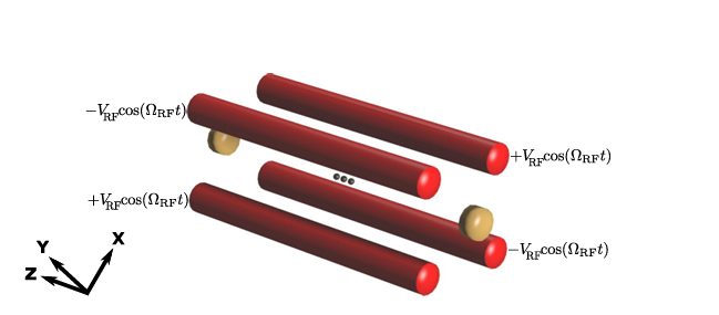
Figure 1: Schematic of an RF Linear Paul Trap
Red: Electrodes applying RF voltage; Yellow: End-cap electrodes generating a static electric field to confine the potential along the longitudinal axis; Gray: Representation of charged particles aligned along the z-axis, where the RF electric field is ideally zero. (Image source: Benjamin Szymanski, "Piégeage et refroidissement d’ions strontium dans des pièges micro-fabriqués," PhD thèse, December 4, 2013.)
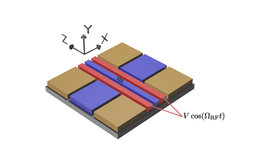
Figure 2: Schematic of an RF Planar Linear Paul Trap
Red: Electrodes applying the same RF voltage; Yellow: Electrodes generating a static electric field to confine the potential along the longitudinal axis; Blue: Static voltages applied to other electrodes to form longitudinal confinement; Gray: Representation of charged particles aligned along the z-axis. (Image source: Benjamin Szymanski, "Piégeage et refroidissement d’ions strontium dans des pièges micro-fabriqués," PhD thèse, December 4, 2013.)
After trapping, ions must be cooled to near their quantum mechanical ground state using laser cooling techniques, which is essential for precise quantum operations.
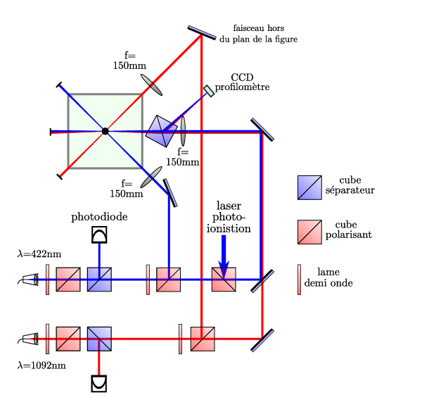
Figure 3: Optical System Layout of a Trapped-Ion Quantum Computing Platform.
The optical system layout of the trapped-ion experimental platform is shown in the figure. The green area represents the ultra-high vacuum chamber containing the ions (represented by black dots). Cooling (422 nm) and re-pumping (1092 nm) beams are transmitted to the platform via polarization-maintaining fibers (see Figures 4 and 5). After polarization filtering, part of the power is monitored by photodiodes for real-time power servo control. Each beam is then split into two paths: one combines the 422 nm and 1092 nm lasers on the first axis parallel to the trap surface for ion cooling, along with the photoionization laser; the other directs the repumping laser at a 25° angle to the vertical axis. The second cooling beam is incident at a 45° angle parallel to the trap surface. A CCD camera is used to monitor the beam profile in the trapping region, ensuring precise alignment. (Image source: Benjamin Szymanski, "Piégeage et refroidissement d’ions strontium dans des pièges micro-fabriqués," PhD thèse, December 4, 2013.)
Through Doppler cooling and sideband cooling, the kinetic energy of the ions is reduced to the microkelvin (μK) level.
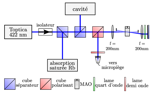
Figure 4: Optical Configuration of the 422 nm Cooling Beam (Key Components Only)
A saturated absorption module is used for laser frequency servo control, transferring the frequency lock to the 1092 nm repumping laser via an optical cavity. An acousto-optic modulator (AOM), driven by a voltage-controlled oscillator (VCO) at around 220 MHz, enables laser frequency tuning within ±0.5 MHz (limited by VCO nonlinearity). The beam is coupled into a polarization-maintaining fiber and transmitted to the ion trap experimental platform. (Image source: Benjamin Szymanski, "Piégeage et refroidissement d’ions strontium dans des pièges micro-fabriqués," PhD thèse, December 4, 2013.)
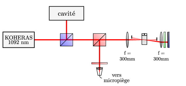
Figure 5: Configuration of the 1092 nm Repumping Laser (Key Components Only)
An optical cavity transfers the frequency lock from the 422 nm laser to the infrared laser and adjusts its frequency. The AOM operates at a fixed frequency of 100 MHz, and the beam is coupled into a polarization-maintaining fiber and transmitted to the experimental platform. (Image source: Benjamin Szymanski, "Piégeage et refroidissement d’ions strontium dans des pièges micro-fabriqués," PhD thèse, December 4, 2013.)
Next, optical pumping techniques are used to initialize the ion's electronic state to a specific quantum state (e.g., the ground state |0⟩ or |1⟩) with a fidelity exceeding 99.9%. Laser manipulation is then employed to perform quantum logic gate operations, such as single-qubit gates and two-qubit entangling gates.
Single-qubit gates are achieved by driving electronic transitions with laser or microwave pulses, while two-qubit gates rely on collective vibrational modes (phonons) as intermediaries, using laser-induced dipole interactions (e.g., Cirac-Zoller or Mølmer-Sørensen schemes) to generate entanglement. These operations achieve fidelities of over 99.9% and 99%, respectively.
Quantum state readout is performed by exciting fluorescence signals with resonant lasers, and the difference in photon scattering between ground and excited states is detected by high-sensitivity detectors, with an error rate below 1%. To extend system coherence time and suppress noise, dynamic decoupling pulse sequences and quantum error correction codes (e.g., surface codes) are used to actively correct errors.
Challenges in Optical Systems for Trapped-Ion Quantum Computing
Precise laser control and fine environmental control are critical for maintaining the stability and coherence of qubits. Any minor distortion (e.g., defocus or aberration) in the optical system can significantly increase quantum gate error rates.
Phasics High-Resolution Wavefront Sensors Provide Key Support in the Following Dimensions:
1. Comprehensive Beam Quality Diagnosis and Real-Time Alignment:
2. Real-Time Alignment and Stability Control:
3. Micro-Nano Characterization of Photonic Devices:
4. Engineering Design for Quantum Laboratories:
SID4 UVHR for Spectral Range UV (190 - 400 nm), SID4 HR for Spectral Range VIS - NIR (400 - 1100 nm).